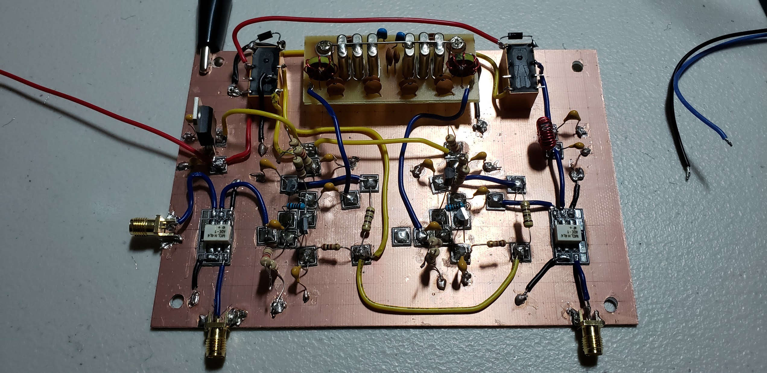
The MB 20 transceiver is now complete. The rig is a homebrew 10-watt 20-meter SSB transceiver. The VFO module was an ebay purchase of a salvaged Yeasu FT-401B module. The FT-401B was manufactured around 1970. I bought the module after a recommendation from Bill Meara, N2CQR and Pete Juliano, N6QW. The rig was loosely inspired by Bill’s Mythbuster rigs.
This rig is really a stone-soup build – with bits and pieces of modules lifted from or inspired by many of the homebrew illuminati!
The Yaesu VFO runs at 9MHz so I set the IF at 5MHz and built a 5MHz crystal ladder filter. The rest of the IF module consists of 4 Termination Insensitive Amplifiers (TIAs from W7ZOI, Wes Hayward), 2 on either side of the filter for each of transmit and receive. I also used a TIA to boost the output of the Yaesu VFO by 7dB to drive the IF mixer. The BFO is a Colpitts crystal oscillator using one of the crystals left over from the ladder filter build. The IF mixer is a homebrew diode ring mixer. The balanced modulator / product detector is a 2-diode circuit that I liberally borrowed from Ashhar Farhan’s Bitx-20 module schematic. The power chain is two 2N3866 pre-amp/driver stages feeding a RD06HHF1 MOSFET final amplifier, very loosely modeled after the Bitx-40 module PA. The 20-meter band pass filter is a standard double tuned circuit, the Tx LPF is a W3NQN LPF design with values taken from the QRP Labs kit instructions. The microphone amp is a one transistor NPN amp configured to support a homebrew electret microphone. The circuit originally came from Farhan’s sBitx that I modified for my electret mic. The audio amp is a single stage driver and an LM-386, that I first built for Pete’s SimpleSSB.
The front panel and base are plywood from my wood shop. I use copper roofer’s foil to create a solderable ground plane. Almost all the circuit boards are homebrew Manhattan style. The IF TIAS are on boards that were sent to me by Todd Carny, K7FTC, of MostlyDIYRF. The Tx/Rx switching is relay based.
Lastly, the digital frequency display is Ardunio Nano and a surplus TV prescaler chip that divides the IF frequency by 64 so that it can be counted by the nano. This is my revision of a circuit described by IMSAI guy on his YouTube channel that has also been build by many others. I rewrote the firmware to provide a rock solid frequency display with 100 Hz precision. The digital display makes fine tuning the VFO much easier – and its very good to be able to tell at a glance where I am tuned to. The red 3D printed bezel for the OLED display was designed by my friend Leon, NT8B
It puts out about 10 watts. I plan to build an external 100 watt amp to accompany it, but I have been making QRP contacts just about every day into an off-center fed dipole up at about 35’.
As Pete always says: “If you know stuff, you can do stuff”
And as Bill says: “There is a lot of soul in this machine.”
This week's homebrew adventure was to complete the receiver side of what I am now calling the KK4DAS MB 20 transceiver - MB is a call-out to Bill, N2CQR's Mythbuster rigs which this build is both inspried by and patterned after.
First order of business was choosig the IF freqency which was easy in this case. The VFO is at 9MHz so if I put the IF at 5MHz, well my 2nd grade math teacher taught me that 9+5=14 - which puts me right in the 20 meter band.
I ordered a batch of 5MHz crystals from Mouser for the IF but they had not come in yet - and I was impatient to get started so I built the BFO and balanced modulator using a crystal from the junkbox figuring I would swap in a 5MHz crystal when it arrived. The BFO and two diode balanced modulator is copied directly from Farhan, VU2ESE's original BITX20 schematic. It went together easily. Despite conventional wisdom I did not attempt to mach the diodes - I just took the first two off the tape.
BFO and balanced modulator
Nulling out the carrier
To null out the carrier I injected a 2MHz signal into the AF port of the modulator and put the scope on the IF port. Using the FFT mode of the scope I was able to clearly see the carrier and mixing products. I was able to effectively null out the carrier using the trimmer cap and trimmer pot that are part of the design. The two peaks either side of the middle are the first sum and difference mixing products. The display is centered on the carrier frequency and you can see that it has been nulled out.
The crystals arrived and the next job was to build the crystal filter. I used the Dishal crystal ladder filter design software to design a 6 pole Cohn/QER filter. The advantage of the Cohn filter is that it uses a single value of capacitor between each crystal. The QER (Quasi Quasi Equi Ripple) modification to the Cohn adds an addtional crystal in parallel at each end of the filter and reduces the amount of ripple. When building a filter the recommendation is to pick crystals fom your batch that are the closest in frequency to each other and the Dishal software requires you also to know the motional parameters for the crystal. I used what is called the G3UUR method to evaluate the crystals. I had previously built the simple crystal evaluation circuit and quickly sorted the crystals. I then used the Dishal software to determine first the motional parameters and then to calculate the capacitor values and input/output impedance of the filter. The calculated input and output impedance were spot on0and I calculate the LC values needed for matching to 50 ohms.
Sorting the crystals using the G3UUR circuit
The completed 5MHz, 2.5KHz filter
The last board I needed for the receiver was an audio amplifier. I opened up by box of "boards that could be rigs someday" and found an audio amplifier stage I had built for Pete, N6QW's SimpleSSB a few years ago. Its a single 2N3904 pre-amp followed by an LM-386. With all the boards needed for the receiver at hand it was time to connect everything up.
The completed KK4DAS MB 20 Receiver
I placed the crystal filter at the rear center with the MostlyDIYRF TIA IF amplifier boards on either side. I left space adjacent to the TIAs for the transmit IF amplifiers. The audio amplifier is on the lower right and just above that is the BFO / balanced modulator board. The receive band pass filter is on the upper left below the first IF amp. At the far left is the future Tx RF amplifier stage - not yet wired into the circuit. I mounted the antenna connector on a piece of single sided PCB. To keep the DC wiring straight I decided to use blue wire for DC on Rx and yellow wire for the DC on Tx. Red is used for always on DC.
A big advantage of modular construction is that since all of the modules have been tested individually it increases the liklihood that the build will work well when everything is connected. To my great pleasure that turned out to be the case and the receiver woked perfectly on first power up. There was one glitch - the tuner maxed out at 14.260 MHz about 100KHz short of covering the entire 20 meter band. I thought I was going to have to rebuild the IF with 5.2MHz crystals but Bill pointed out that Yaesu and built in a variable cap to move the VFO passband up or down. I zeroed out the capacitor and that gave me full coverage across 20 meters.
Adjusting the Yaesu VFO for full coverage on 20 meters
Now that the receiver is built I will spend a few nights following Farhan's advice and take pleasure in listening to the receive I have just built.
All I need to build for the transmitter is a microphone amplifier and the final low pass filter. Then add some relays for Tx/Rx switching and then I can work on fit and finish of the cabinet.
The homebrew sBitx is now on the 64 bit version of the OS and software. Thanks to W9JES, JJ and team for their work on this upgrade to the factory sBitx Raspberry Pi image and sofware distribution. JJ and team have made some significant upgrades to the core - most important bringing it to the lates stable 64 bit release of the OS. In addition JJ has developed a suite fo add on applications that provide additional functionality. When I first booted it up I was not able to decode FT8 sigals in teh native sBitx app. JJ worked with me and we found that since I did not have a RTC clock installed the new version of the app was not using the correct time - and for the WSJT protocol to work the time must be in sync wiht UTC. He made the fix so the software will fall back to NTP if no RTC is installed and I am back in business! Thanks JJ.
While I was testing the 64 bit build the rig begain to exhibit another RFI gremlin - the Tx/Rx relay would begin to click randomly - sometimes one click at a time and other times it became a real chatter - annoying enough that I temporarily disconnected the connection from the Pi to the relay so I could get on with testing. I thought it was RFI from the Pi -- maybe related to the Pi's wifi - it seemed to get better when I turned off wifi. My build of the sBitx puts the rig in to Tx by putting a signal on a GPIO line that goes through a dropping resisitor to the base of an NPN transistor that turns on the relay. I suspected RFI was getting into the GPIO line. I put the scope at the base on it and I could see the voltage spikes that were triggering the relay. I put a .1 cap to ground where the line connects to resistor. That didn't help. I put ferrite beads on the line. That didn't help. I switche from a single piece of stranded wire to shielded coax. That didn't help. So I did what I often do when stuck on a thorny circuit problem, I asked my friend Pete, N6QW. Once again the Wizard of Newbury Park diagnosed my problem fromm across the country.
Here is Pete's response in its entirety:
"It may be a case of subthreshold conduction (a leaky transistor),
I would do the following.
Use a 2.2K versus a 220 Ohm. Get some small ferrite beads and slip those over the base lead and change out the 2N3904 transistor to a TIP31C.
Your narrative indicates it is a recent problem and you didn’t see spiking on the GPIO. The signs suggest a leaky transistor (or not). But the above steps are positive and should be done as good practice.
Leaky transistors are not limited to digital electronics and in fact this problem is in the analog hardware."
I didn't have a TIP31C in the drawer and since it was working previously I replaced the no-brand 2N3904 with a new known-good one from my MOUSER hoard, I changed the resistor value per Pete's advice and left the ferrite beads on the signal line.
Bob is my uncle! No more chattery relay. Key point above - this is an analog circuit problem that likely had little or nothing to do with the digital circuit - subthreshold conduction just means the transistror turns on when it is not supposed to.
After a long hiatus I am back at the blog. I have a number of projects that I have been working on that I will share going forward, but today I want to talk about my latest project - a homebrew version of the SBITX transceiver designed by Ashhar Farhan. The SBITX is a hybrid analogue superhet transceiver / software defined radio. The analogue portion of my build is based on the Furlough 40 / SimpleSSB that I built in 2020. The SDR software runs on a Raspberry Pi 3 or 4 with software written by Farhan. I'll explain the title of the post before we are done today but first lets take a look at the KK4DAS SBITX.
Here is a demonstration made shortly after I completed the receiver:
For a quick overview of how it works, lets look at the block diagram.
Beginning with the antenna on the upper right let's follow the received signal path. First we pass through a single 30 MHz low pass filter which passes the entire HF band. We amplify the incoming signal with a broad band RF amplifier and then pass it through and ADE-1 mixer to mix the signal up the the 40MHz IF. The LO and BFO clocks are provided by an SI-5351 PLL controlled by the Raspberry Pi. The homebrew 40MHz crystal ladder filter is 25KHz wide which controls how much of the spectrum you can see on the waterfall display at any one time. The bidirectional IF board I am using is the first board I built for the SimpleSSB at the beginning of 2020. I have replaced the 9MHz commercial filter with my homebrew 40MHz filter. The second mixer then drops the signal to a 24Khz IF which is well within the range of the ADC in the codec board. From the second mixer we go through a low noise amplifier to boost the signal and pass it in to the left line-input channel of the codec. The 24KHz signal is digitized in the codec and passed on to the Raspberry Pi where further signal conditioning and filtering occurs, the waterfall display is generated and the digital audio is extracted. The digital audio is sent back to the codec where the digital to analog conversion occurs and the analog signal is sent out the left line output to headphones or to an amplified speaker. The SBITX software also supports FT8, RTTY and CW decoding natively - no additional software or computer is needed. For a detailed description of the SBITX you should read Farhan's SBITX description linked above. Transmit will work much the same but in reverse. I'll cover that when I get the transmitter implemented.
I'm very happy with how the receiver is performing. Its fun to listen to and sounds great. But getting to this point has not been without a few stumbles and sidetracks. I was honored to be included as a guest on the SolderSmoke Podcast Episode #250 with N2CQR, Bill Meara and N6QW, Pete Juliano where I shared my tales of woe - a few of which I will describe here in more detail and a others which I will save for another day.
Ground Bounce - shortly after completing the receiver I made the unsettling discovery that signals that were being transmitted on 20 meters were being received on 20 meters but also at exactly half the frequency on 40 meters. This was not good - it seemed that it had to be strange mixing products in the first mixer, but I had tested the entire IF before hooking it up to the digital board - and this very same IF board was pulled from a working receiver. I looked at the output of both mixers and I couldn't see how the the 20 meter signal was leaking in on 40. After thinking about it for a bit I decided to look at the SI5351 outputs on my TinySA Ultra spectrum analyzer and instead of seeing one clean signal on each of the LO and BFO clocks I saw both signals on both clocks. This was clearly the source of my problem. Skipping over a day or two of troubleshooting I sent a note to Farhan and he immediately identified the problem. It was "ground bounce. Apparently if the clock outputs are not properly grounded it causes current to rise internal the SI-5351 and signals to bleed between the clocks. In following a separate piece of advice from Farhan on buildiing the digital board I had very carefully insured that there was one and only one ground connection in the digital board and that was directly back to the main DC input. I had installed the SI-5351 directly onto the digital board and it shared that common ground. But that meant that I couldn't also ground both ends of the coax shield between the SI-5351 and the mixers. That was the cause of the ground bounce. The solution was to remove the SI-5351 from the digital circuit and put it on the analog circuit - with the only connection between the SI-5351 and the Raspberry Pi were the two I2C control lines. And also to ground the coax connecting the SI-5351 and the mixers at both ends. That fixed it - the ground is no longer bouncing!
Hallucination - after curing the ground bounce I spent an evening listening to the rig enjoying the glow you get after fixing a thorny problem. But my enjoyment was short-lived. I noticed that from time-to-time that the waterfall display would go a little crazy,. It appeared as if the the receive signal was being duplicated all up and down the band somewhere internal to the SBITX. It looked like this:
The signal at the center is the received signal - all of the mirror images are false. Those are the hallucinations. Farhan identified that fairly quickly and let me know about a software fix in the SBITX 3.2 which led me to:
Wisdom - I don’t have a complete understanding, but the hallucinations are artifacts created during the Fast Fourier Transform of the received signal under certain circumstances. The SBITX uses the open-source FFTW (Fastest Fourier Transform in the West) library. There is an extension to the FFTW library called FFTW-Wisdom that is used tune the FFT algorithm the first time it is used. The tuning parameters are saved in what is known as an FFT “Wisdom” file . The Wisdom file, which only has to be computed one time, contains saved information about how to optimally compute Fourier transforms of various sizes. The FFTW Wisdom File man page has more details. That was what was implemented in SBITX V3.2 which eliminated the hallucinations.
I'm still chasing a few problems in the receiver. Top of my list is a tuning problem. When I zero beat WWV on exactly 10 MHz, the displayed frequency on the SBITX is a few hundred Hz off of 10MHz, and when I tune to 15MHz WWV the display is off by a different amount. So, the delta between the displayed frequency and the frequency the radio is receiving changes with frequency – but not in any linear way. I’ve tried several different ways to align the radio but have not yet been successful The last thing I did was disconnect the analog receiver entirely from the SDR and used a signal generator to put a fixed 24KHz signal into the audio codec which should result in a signal displayed dead center on the waterfall – but it did not – it is a few hundred Hz off. the current suspicion is that the crystal on my WM8731 protottype board is out of spec. Farhan has offered to send me one of the codec boards he produced for the early SBITX prototype. When that arrives, I will replace my audio codec with the one he sends. That should resolve this last issue but it still doesn’t explain why the delta moves with HF frequency. That’s what was puzzling me and what I was referring to on the podcast.
QRP is great and by far my favorite way to operate - especially since completing my scratch-built Furlough 20/40 QRP SSB and digital mode transceiver. But as my friend Pete, N6QW says, "some days you just want to put on your big boy shoes." For "big boy shoes" for the Furlough I chose to build the Eamon Skelton, EI9GQ 16 watt power amplifier from his book "Building a Transceiver". The amp uses dual Mitsubishi RD16HHF1 transistors in a push pull configuration. This was my first attempt at anything beyond the SimpleSSB IRF-510 amp that I used in the Furlough. EI9GQ's books is a good reference and there are several other builders who have documented their builds online. Here's mine...
Beginning with the schematic - I used EI9GQ's specification. The transformers gave me pause and I had to really "noodle" over their construction. In addition to figuring out the windings and interconnections, if you read the article EI9GQ recommends torroids and shielded wired that do not seem to be available anymore. For transformer T3 he specifies HEM3011 torroids, I substituted two FT50-43s glued together for each side of the transformer, I also just used #26 AWG for the bifilar turns rather than the shielded audio cable that he recommended.
The next thing to do was to figure out the transformer windings and start to think about layout. Using my primitive graphic arts skills I sketched out each transformer and carefully number the wires. This proved very helpful when it came to construction. Here you can see my layout and tentative parts placement on the top of the heat sink. I made the board about 1/2" longer than the heat sink in both directions to allow for overhang of the SMA connectors I intended to use.
I've been using a CNC mill to carve PCBs for Manhattan style builds for a while and I do my layout in a free program called Carbide Create. It's fairly easy to use and combines the editing package with a G-code generator to produce the program for the CNC mill. Here is my layout.
I always print an an actual size image of the board to check for part fit. This save a lot of time and wasted PCBs if the parts don't fit. For this build I milled the traces for the voltage regulator and bias trimmers, cutout the center square for the transistors and drilled some mounting holes. I decided to wait until construction time to attach Manhattan pads for the components. EI9GQ used mostly u\Ugly construction with all the non-ground connections in the air. I prefer a pad to solder to most of the time but this time I kept my options open. I ended up doing some Ugly construction and some on pads.
Once I was happy with the layout it was time to fire up the mill and get carving. The PCB carve took about 20 minutes. Enough time for a cup of coffee and to contemplate life.
Next up - drilling an tapping holes to attached transistors and PCB to the heat sink. Two trips to the Depot - one for the #6/32 tap and one for the tap handle since my other one didn't clamp down on the small tap.
With the PCB attached to the heat sink it was time to start laying down parts. I started with SMA connectors, transistors and DC bias circuits - leaving the exact placement of the transformers until I had a better feel how everything would go. My only wiring mistake is visible in this next picture. I had soldered the 8 volt regulator in backwards,
I glued down a few hand cut Manhattan pads and soldered up all the components on the input side of the the amp. I attached the input coils. At this point the amp was about 90% complete - I just had to attach T2, the DC wiring for the drains and T3. And also to maker sure I got the transformer connections right.
Amp done and ready for testinng.
And here is a demo of the recreated smoke test. Much to my delight, after correcting the orientation of the voltage regulator that amp worked straight away. With the transistors biased at 500mA each I measured just over 13dB flat across the entire HF amateur radio spectrum,
The next step will be to replace the IRF-510 stage of my Furlough with this amp and see how it works on the air. As I mention at the end of the video I suspect I'll need to add another driver stage to get enough drive for the full 16 watts.
After close to two years of working on projects I'm starting to realize that Pete's adage - "if you know stuff, you can do stuff!" is really true. It has been a steep knowledge climb for me - but I'm starting to feel it.
Just a quick post to share an exciting update on the Vienna Wireless SimpleSSB project. Three member of the VWS held an impromptu 100% SimpleSSB QRP net the other day in preparation for a presentation at our club meeting last night. KA4CDN, Mike. KM4UDX, Don and I had a brief QSO to record or progress for posterity.
After about 6 months of work 16 members of the Vienna Wireless Society Maker's group have successfully completed our 100% scratch built 40 meter SSB QRP receivers and 8 of the group have full up 5 watt SSB and digital mode transceivers. The group has now racked up hundreds of QSOs including many DX to Europe, Central and South America and most US states. With FT8 and other digital modes we have confirmed QSOs from around the globe.
Here are just a few of the finished rigs...
As background - if you've followed my infrequent blog posts you know that the group started a group build of the of N6QW Pete Juliano's SimpleSSB QRP transceiver about 6 months ago. Check it out!
It has been too long since the last update but I have some exciting news and also a classic homebrew “tale of
woe” to share.
First, my friend Mike KD4MM, here in Vienna, VA was the
first member of the Vienna Wireless Society Makers group to complete the
receiver side of N6QW, Pete Juliano's SimpleSSB transceiver – check it out:
Mike shared his progress with us and also this demonstration
of decoding FT8 with simple audio coupling:
And the tale of woe shared by Don, KM4UDX, reminds us that
not everything goes smoothly when building a homebrew transceiver. He
reminds to “Don’t do what Don Did!”
It has been just over a year since I completed my initial build of the Furlough 40 with much coaching and assistance from Pete. Mike and Don are two out of 20 members of the Vienna
Wireless Society Makers group that is working on a group build the SimpleSSB project as enhanced by me to include features like CAT control for
digital modes. Beginning about six weeks
ago the group is progressing module by module per SolderSmoke best practice
advice. We started with the audio amplifier, followed that with the
Arduino/SI-5351 based controller module and the builders are just completing
the IF module. This week at our weekly meeting, Mike proudly showed off
his success.
Pete was gracious enough to provide tribal knowledge and
encouragement to the group a view weeks ago:
The group is generating a ton of great material on the
project including photos and videos of the in-progress builds, technical
documentation, test equipment, procedures and more.
Here just a few pictures of the in-progress builds
Just think of this – in another couple of weeks we may have
as many as a dozen SimpleSSB transceivers on the air…..we are giving serious
competition to the big rigs everywhere.
And a very warm welcoming of to the new members of the much sought after, rarely granted membership in to the International Brotherhood of Electronic Wizards.
I've been working steadily on the revising the Arduino code for the Furlough 40 Homebrew 40 meter SSB phone transceiver that I built earlier this year based N6QW, Pete Juliano's Simple SSB. Last time I described the code for a color TFT module to use as a replacement for the 4x20 LCD that I originally used and I promised to upload additional modules. The code for a fully functional ham radio control program is complete. I need to finish documenting it and will post it to my github page. In addition to the display module already posted I plan to post on each of the remaining modules required to produce a fully functional SSB control program including the SI-5351 produced LO and BFO clocks. This control program should be straightforward to adapt to a variety of homebrew radio projects. The modules that I will be provide and document are:
Display Modules
TFT Display
Nextion Touch Screen Display
4x20 LCD Display
Button Handler (hardware buttons and switches)
Encoder - handles the rotary encoder and push button
While I was putting the final touches on the CAT control code for the F40 I received an email from Pete asking me about programming a Nextion Touch Screen display. I had a spare in the junk box. I had purchased two when I upgraded my uBix V6 to the wonderful uBitX Nextion module provided by KD8CEC, Ian Lee. That upgrade was plug and play since KD8CEC provided all the code. When I got Pete's email I loaded up the Nextion IDE and cobbled together a "LED On, LED Off" sketch which is the Arduino version of "Hello World." The Nextion IDE and programming library are available for free on the Nextion web site. It requires a bit of fiddling and a learning curve to get it going and I will fully describe in a future post. I sent off the code to Pete and he asked about how to include a frequency display. I did that in about five minutes and that inspired me to try to build the F40 user interface. Since I had recently completed the TFT Display Module I already knew what functions I needed to implement for display side of the interface. As a reminder, the display functions are things like:
DisplaySetup
DisplayActVFO
DisplayAltVFO
DisplayVFOAB
DisplayTxRx
DisplayMode
DisplayIncr
DisplayTune
One of the cool things about the Nextion IDE is that it allows you to build and simulate what you will eventually see on the screen - and it is all drag and drop with very little programming is required. The Nextion communicates with Arduino Sketch via a simple protocol running over a serial interface.
Since I already had two working display modules built (for the 4x20 LCD, and for the color TFT) I already knew what I needed. Within about two hours I had fully reproduced the functions of the color TFT display. Buttons and switches are also easy to implement; a couple of hours later I had reproduced the front panels switches from the F40 - VFO A/B, LSB/USB, and TUNE. That was another couple of hours. So in about half a day I had created a fully functional touch screen display for the F40. The only physical change to the F40 was disconnecting the LCD and connecting two wires to the Arduino plus power. Not bad at all!
Based on that success I began work on extra features that I had put off adding to the F40 because they would require either complicated menus or a bunch of other hardware buttons. The first thing I added was the ability to work Split (transmit on one frequency and receive on a different frequency). One button (five minutes) - and about 30 minutes to write the code on the Nano to switch the clock frequencies on the SI5351. I previously described my approach to modular programming and since I had already written the VFO/BFO control module it was a matter of a few minutes to code that up. I then added a Scan button to scan through frequencies and this was interesting - I was able to add that function by just making changes on the Nextion - no Arduino programming required.
More on Nextion programming later - but for now, please take a look at the video and let me know what you think in the comments.
APRS and the International Space Station
KM4HRR Talks to the ISS
On Sunday, my friend KM4HRR Brendan invited me to see the progress he has made in contacting the ISS using APRS. His setup is the following:
Kenwood TH-D74 Transceiver, with an ISS profile that he created
At about five minutes before the pass, ISS Detector sent an alert. Then, using the iPhone camera, also controlled by ISS Detector, he pointed the antenna at the horizon. Right on time, he received an APRS beacon from ISS and over the next few minutes Brendan sent and received several APRS messages. He had added several macros to his ISS profile on the TH-D74 to make it easy to send messages during the 5-6 minute pass.
All in all, a pleasant way to to spend and hour. I now may have to invest in an APRS capable HT!
Farewell Neowise, we barely knew ye....
In keeping with the space theme, when I am not playing radio, I play photographer - and here are two of my favorite captures of comet Neowise at nearly its closest approach to earth.
I wanted to liven up the display module for my F40 - the 4x20 LCD display is certainly functional, but decidedly industrial in look. I have gotten quite fond of the color display on my uBitx, so I decided to build a color display module for the F40. I opted for a color TFT for the display since they are ubiquitous, inexpensive and there are many good Arduino libraries that make programming a snap. Uber Elmer N6QW, Pete Juliano graciously shared with me the sketches he had written for various color TFT projects and I downloaded and also evaluated sketches from several other hams. Not quite finding what I wanted, I decided to write my own sketch.
I should let you know that I'm a relatively young ham (60 years young, but licensed only two years ago), but I am a very old software guy (still 60, but have been a professional software engineer and executive for 40 years). So, when I started looking at source code for Arduino sketches that were written by amazing hams with no formal software training I knew I had to dive in.
My design goals for the project were the following:
The code must follow sound software engineering principles throughout.
It must be modular and reusable. To be easily reusable the code most not be dependent on any particular hardware design. You should be able to drop it in to any Arduino based radio control program with minimal effort.
It must have a small memory foot print and not use up much of the Arduino's precious dynamic RAM.
It must be fast and not tax the Arduino microcontroller- we want to save its CPU cycles for control of the rig.
It must use standard Arduino display libraries and be relatively hardware independent - easy to port to a different display or microcontroller.
It must be easily reconfigurable - you should not have to change code to make simple user interface changes like screen colors and font sizes.
It must provide the basic display functions for a dual VFO SSB rig - and that means dual VFO display, active VFO indicator and LSB/USB indicator.
It must be easy to add new display elements - including an S meter and other similar displays.
And last, the code must be easy for a non-professional coder to understand and work on. No tricks or fancy code footowork.
So, over the long memorial day weekend I wrote and tested the KK4DAS SSB TFT Display.
A quick note if you are interested in building this. This is not a complete radio control sketch - it is only the display module. Over the coming weeks I will publish additional modules that will implement a complete SSB transceiver controller. But for now, all you need is an Arduino and a color TFT, and possibly some level shifters. The Arduino nano uses 5V logic but the TFT needs 3.5V logic so the level shifters are used to take care of that. You'll also need to install the Arduino IDE and load the two required libraries.
Here are some of the details:
Features
Basic radio display panel for an SSB transsceiver
Designed for a 320x240 Color TFT (non touch)
Tested with an ILI9341 display
Requires the following libararies
Adafruit_GFX
Adafruit_ILI9341
Implements a basic SSB display console with the following features
 Dual VFO A/B
 Mode indicator  SSB/LSB
 Tx/Rx ndicator
 TuningStep Inidicator
 S Meter
 Banner including Call sign

 Fully customizable. Fast display makins use of minimal resources./
 Room is left on the screen for additional features
 There is room on the screen for another row of features

 Easily change colors, font sizes and layout
Default Screeen Layout
  ____________________________________
  |       A 7.200.000 LSB             | -- VFO A/B indicator, Active VFO Freq, LSB/USB inidicator
  |      Rx 7.048.000 100K            | -- Rx/Tx indicator, Alternate VFO Freq, Tuning Increment
  |                                   |
  |      S |_|_|_|_|_|_|_|_|_|_|_|_|  | -- S Meter
  |         1   3   5   7   9         |
  |                                   |
  |        AGC   SPL   RIT            | -- (Planned) AGC on/of, Split On/Off,  RIT On/OFF
  |                                   |
  |     Ver   Rig Name   Call         |
  |___________________________________|
This module provides the following radio console display functions:
displaySetup - initialize the display and displays the startup values - call once from your setup function
displayBanner - Displays a text banner across the bottom of the screen
displayActVFO - Displays the frequency of the Active VFO
displayAltVFO - Displays the frequency of the Alternate VFO
displayVFOAB - Displays the indicator which VFO is active (A or B)
displayTxRx - Displays whether the rig is in (Tx or Rx)
displayMode - Displays the which sideband is selected (LSB or USB)
displaySMeter - Displays the S Meter (1-9 are gray, +10 +20 and +30 are red
This module also provides the following general purpose display functions:
displayClearScreen - fills the screen with the selected backgrond color
displayPrintat - prints text or nubmers on the screen at a specific location
displayDrawBoundingBox - draw a box on the screen and fills it with a background color
displayDrawTextBox - displays text inside a boundig box
Design notes and how to use the code
NOTE TO BUILDERS
This is not a complete radio control sketch. It is the Display software only. In the spirit of modular design
it is stand-alone and not dependent on using an SI-5351 or any other specific hardware, or on my particular
hardware selection of switches, buttons and knobs. The demonstration sketch shows how to update the display, but you need to provide the code to determine what the actual values should be. You will likely need other
libraries like the Si5351 and a Rotary encoder library aside from the GFX and the ILI9341.
DESIGN PRINCIPLES
Good software design principles are to use as few hard-coded numbers as possible. Wherever possible I have used #defines for any number that will be used more than one place in the code. For example #define DSP_VFO_ACT_X 60 defines the X coordinate (how far from the left of the screen)
of the Active VFO frequency display. You will see multiple references to DSP_VFO_ACT_X throughout the code,
but I never use the hardcoded number 60 again. Change it once – and it is changed throughout.
Taking the S-Meter as an example:
To update the S-Meter display you make a call to displaySMeter(n); where n is an integer from 1 to 12
(representing S1-9, +10, +20 +30). Your sketch will need a way of monitoring signal strength (an analog input
pin on the Arduino attached to an appropriate place on your rig) and converting it to the logarithmic S scale.
SCREEN COORDINATES
Coordinates work differently on displays than a typical graph where the origin 0,0 is in the middle abd positive
and negative values move you away from the origin. For displays 0,0, the origin, is always upper left hand corner
of the display and you only use positive numbers for the coordinates +X is pixels from the left edge, +Y is pixels
down from the top. This particular example based on a 320x240 display but should be easily portable to other
display sizes – but you have to keep in mind how the coordinate system works.
SCREEN LAYOUT
Here are a few notes about how the demonstration display is laid out. This should help you understand the design
concept and allow you to begin to modify it.
The VFO display is setup for a dual VFO rig. The currently Active VFO is always on the top and the alternate VFO
is just below it. Your code will need to keep track of whether VFO A or VFO B is currently selected and call the
display routines to update the display. I’ll describe how the VFO displays are are defined and that will give you
an idea how you might modify or enhance the display.
Active VFO - top center of the screen
#define DSP_VFO_ACT_X 60   // Active VFO begins 60 pixels from the left hand edge (I picked 60 by experimenting)
#define DSP_VFO_ACT_Y 30   // Active VFO box starts 30 pixels down from the top of the screen
                          // (Try changing it to 50 and see what happens)
#define DSP_VFO_ACT_COLOR ILI9341_GREEN   // This sets the text color for the Frequency display. Use whatever colors you like
#define DSP_VFO_ACT_BK ILI9341_BLACK      // This sets the background color for the Active VFO
#define DSP_VFO_ACT_SZ 3                  // This is text size from Arduino TFT, values 1-5 1 is small 5 is large (2 was too                                                 // small, 4 was too large, 3 was just right)
Alternate VFO – the second VFO is placed directly below the Active VFO on the screen.
There are a couple of things of interest here. For the X coordinate, instead of putting in a hard coded number I refer back to
the #define that I used for the Active VFO (DSP_VFO_ACT). That way, if I want to move VFO section to a different part of the
screen I only need to change one number DSP_VFO_ACT_X, and the alternate VFO will move as well. Figuring out the Y coordinate
for the alternate VFO is a little more challenging. Some math is involved. Starting with the Y coordinate of the Active VFO
I need to calculate where how far down the display I need to go to place the second VFO. To do that I need calculate
how many pixels tall the text characters in the Active VFO are and use that as an offset. It turns out we have everything
we need already defined. CH_W and CH_H are #defines that specify the height and width of a text character in pixels for
TFT font size 1. Size 2 through 5 are even multiples of that – so font height for size 2 is
2*CH_H pixels and font width
And for size 4 is
4*CH_W
pixels and so on. so we have everything we need to calculate how many pixels the Active VFO takes
on the screen – we multiply the font size by the character height and add 16 pixels offset. The 16 was determined by
experimentation for something that looked good. The code looks like this:
Take a look the other sections of the display code and you will see similar references and calculations. The VFO A//B
indicator and LSB/USB mode indicator, for example are similarly “pinned” to the Active VFO display, so if you move the
Active VFO display to another screen location they will move also.
In summary - each object is on the display is defined by a set of constants that indicate the X,Y coordinates
of the object on the screen and various other attributes like text size and color. The basic user interface display
object is a bounded/filed text box. You can control the text size and color, and the box fill color. With this basic
set of features you can implement a wide variety of user interface elements. The S-meter, for example, is a row of
filled boxes.
HARDWARE NOTES
My test sketch uses an Arduino Nano. The display is an HiLetgo 2.2 Inch ILI9341 SPI TFT LCD Display 240x320,
but any ILI9341 display should work. There are many sources. Please note that the Arduino has 5V logic levels,
but the display requires 3.3V - so you need some sort of level shifter. I used the"HiLetgo 10pcs 4 Channels IIC I2C
Logic Level Converter Bi-Directional 3.3V-5V Shifter Module for Arduino" I used hardware SPI and the pinouts are
standard as follows:
        Arduino
         Pin       TFT Pin
      -----------|---------
          8      |  RST  - any free Arduino Pin (not used in this sketch)
          9      |  DC   - any free Arduino Pin
          10     |  CS   - any free Arduino Pin
          11     |  MOSI - fixed
          12     |  MISO - fixed
          13     |  CLK  - fixed
That is all the wiring you need for the demonstration sketch.