I've had several comments over the last 24 hours to the effect of - "it looks good, but how well does that pretty red roadrunner work on the air?"
Here is one so you can hear it for yourselves.
I've made a couple of dozen contacts putting on the air with very good signal an audio reports. Here is one memorable one with the W8A special event station celebrating the 21st amendment to the US Constitution. The 21st amendment repealing prohibition in the United States was ratified on December 5, 1933 - thus my opening comment about striking a blow for liberty.
It is often the case that when I tell someone that "the rig here is homebrew" they can't quite get their head around the idea that hams still build radios. I've also noticed that if I ask for a signal and audio report after they know it is a homebrew rig they are much more critical of the audio - "sounds pretty good for a homebrew" is something every homebrewer has heard. One contact was so astonished he accused me of surreptitiously running an IC-7300 - I'll take that to the bank.
I've spent the last few weeks putting the finishing touches on what has become the Furlough 2040 Supercharged SSB transceiver. Originally designed and designated the SimpleSSB by my friend and elmer N6QW Pete Juliano I have extended and supercharged his excellent modular design in a number of ways. The final (although Pete advises you should probably never say 'final' when talking about a hombrew rig) configuration is as follows:
20 Watt SSB and digital dual band transceiver for 20 and 40 meter bands
Arduino Nano Every microcontroller and SI5351 clock generator
9 MHz IF - filter
Nextion Color Touch Screen Display
AGC and S-Meter
3 stage Tx amplifier chain, 2N2219A 1st driver, IRF-510 driver stage generating 1-2 watts driver for the 20-watt push pull RD16HHF1 push-pull final amplifier designed by EI9GQ Ed Skelton
Firmware includes full CAT control for digital modes, frequency scanning, persistent frequency and mode memory stored in EEPROM
Custom enclosure with a CNC cut front panel
KK4DAS Furlough 2040 20-Watt SSB and digital mode transceiver
Walkthrough of the transceiver and the final bench test:
Here is a look at the voice modulation envelope:
And a few more pictures to wrap it up:
Final Bench Test
Final assembly in the enclosure - two levels - Tx board on top
On the air peaking 16 watts SSB phone.
This has been an incredible 2-year learning journey. Many thanks to Pete and also to Bill Meara N2CQR of the SolderSmoke podcast who started out humoring me as I built my Michigan Mighty Mite and have become great friends. Also, many thanks to the members of the Vienna Wireless Society Makers group who joined me on the journey at the beginning of the year and we now have about 15 more SimpleSSB transceivers on the air. Watch this space for more on the VWS maker group progress including KA4CDN, Mike's addition of CW just completed yesterday!
Michigan Mighty Mite - December 2019
73 from Great Falls,
Dean
KK4DAS
UPDATE - For those interested in building a similar rig you should know that this is not a kit nor is there a single master schematic or bill of materials. The vast majority of the components are common resistors, transistors, capacitors, voltage regulators, etc. This is a modular build with each module built and tested and integrated as you go along. Each module is well documented and by virtue of the Vienna Wireless Society Makers group build there is a great set of documentation and examples for each module. Where particular components are required (ADE-1 Mixers, SI-5351 clock module, etc) they are called out in the documentation below.
For builders, I highly recommend you build the original SimpleSSB as specified below. This is a 10 transistor, Arduino controlled 5-watt SSB phone and digital mode rig for 40 meters. Once you have the basic rig built then decide which enhancements are right for you.
QRP is great and by far my favorite way to operate - especially since completing my scratch-built Furlough 20/40 QRP SSB and digital mode transceiver. But as my friend Pete, N6QW says, "some days you just want to put on your big boy shoes." For "big boy shoes" for the Furlough I chose to build the Eamon Skelton, EI9GQ 16 watt power amplifier from his book "Building a Transceiver". The amp uses dual Mitsubishi RD16HHF1 transistors in a push pull configuration. This was my first attempt at anything beyond the SimpleSSB IRF-510 amp that I used in the Furlough. EI9GQ's books is a good reference and there are several other builders who have documented their builds online. Here's mine...
Beginning with the schematic - I used EI9GQ's specification. The transformers gave me pause and I had to really "noodle" over their construction. In addition to figuring out the windings and interconnections, if you read the article EI9GQ recommends torroids and shielded wired that do not seem to be available anymore. For transformer T3 he specifies HEM3011 torroids, I substituted two FT50-43s glued together for each side of the transformer, I also just used #26 AWG for the bifilar turns rather than the shielded audio cable that he recommended.
The next thing to do was to figure out the transformer windings and start to think about layout. Using my primitive graphic arts skills I sketched out each transformer and carefully number the wires. This proved very helpful when it came to construction. Here you can see my layout and tentative parts placement on the top of the heat sink. I made the board about 1/2" longer than the heat sink in both directions to allow for overhang of the SMA connectors I intended to use.
I've been using a CNC mill to carve PCBs for Manhattan style builds for a while and I do my layout in a free program called Carbide Create. It's fairly easy to use and combines the editing package with a G-code generator to produce the program for the CNC mill. Here is my layout.
I always print an an actual size image of the board to check for part fit. This save a lot of time and wasted PCBs if the parts don't fit. For this build I milled the traces for the voltage regulator and bias trimmers, cutout the center square for the transistors and drilled some mounting holes. I decided to wait until construction time to attach Manhattan pads for the components. EI9GQ used mostly u\Ugly construction with all the non-ground connections in the air. I prefer a pad to solder to most of the time but this time I kept my options open. I ended up doing some Ugly construction and some on pads.
Once I was happy with the layout it was time to fire up the mill and get carving. The PCB carve took about 20 minutes. Enough time for a cup of coffee and to contemplate life.
Next up - drilling an tapping holes to attached transistors and PCB to the heat sink. Two trips to the Depot - one for the #6/32 tap and one for the tap handle since my other one didn't clamp down on the small tap.
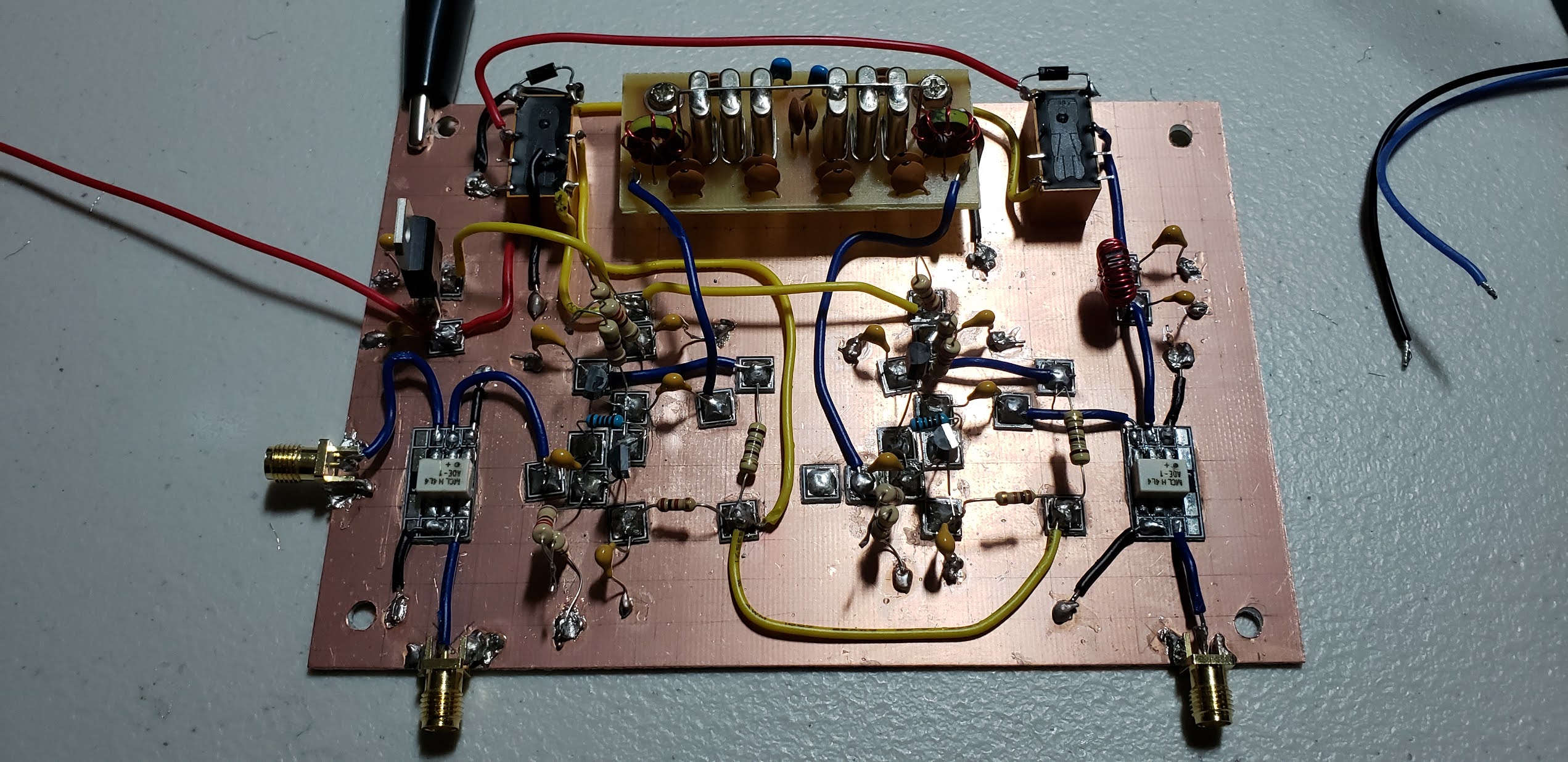
With the PCB attached to the heat sink it was time to start laying down parts. I started with SMA connectors, transistors and DC bias circuits - leaving the exact placement of the transformers until I had a better feel how everything would go. My only wiring mistake is visible in this next picture. I had soldered the 8 volt regulator in backwards,
I glued down a few hand cut Manhattan pads and soldered up all the components on the input side of the the amp. I attached the input coils. At this point the amp was about 90% complete - I just had to attach T2, the DC wiring for the drains and T3. And also to maker sure I got the transformer connections right.
Amp done and ready for testinng.
And here is a demo of the recreated smoke test. Much to my delight, after correcting the orientation of the voltage regulator that amp worked straight away. With the transistors biased at 500mA each I measured just over 13dB flat across the entire HF amateur radio spectrum,
The next step will be to replace the IRF-510 stage of my Furlough with this amp and see how it works on the air. As I mention at the end of the video I suspect I'll need to add another driver stage to get enough drive for the full 16 watts.
After close to two years of working on projects I'm starting to realize that Pete's adage - "if you know stuff, you can do stuff!" is really true. It has been a steep knowledge climb for me - but I'm starting to feel it.
Just a quick post to share an exciting update on the Vienna Wireless SimpleSSB project. Three member of the VWS held an impromptu 100% SimpleSSB QRP net the other day in preparation for a presentation at our club meeting last night. KA4CDN, Mike. KM4UDX, Don and I had a brief QSO to record or progress for posterity.
After about 6 months of work 16 members of the Vienna Wireless Society Maker's group have successfully completed our 100% scratch built 40 meter SSB QRP receivers and 8 of the group have full up 5 watt SSB and digital mode transceivers. The group has now racked up hundreds of QSOs including many DX to Europe, Central and South America and most US states. With FT8 and other digital modes we have confirmed QSOs from around the globe.
Here are just a few of the finished rigs...
As background - if you've followed my infrequent blog posts you know that the group started a group build of the of N6QW Pete Juliano's SimpleSSB QRP transceiver about 6 months ago. Check it out!
It has been too long since the last update but I have some exciting news and also a classic homebrew “tale of
woe” to share.
First, my friend Mike KD4MM, here in Vienna, VA was the
first member of the Vienna Wireless Society Makers group to complete the
receiver side of N6QW, Pete Juliano's SimpleSSB transceiver – check it out:
Mike shared his progress with us and also this demonstration
of decoding FT8 with simple audio coupling:
And the tale of woe shared by Don, KM4UDX, reminds us that
not everything goes smoothly when building a homebrew transceiver. He
reminds to “Don’t do what Don Did!”
It has been just over a year since I completed my initial build of the Furlough 40 with much coaching and assistance from Pete. Mike and Don are two out of 20 members of the Vienna
Wireless Society Makers group that is working on a group build the SimpleSSB project as enhanced by me to include features like CAT control for
digital modes. Beginning about six weeks
ago the group is progressing module by module per SolderSmoke best practice
advice. We started with the audio amplifier, followed that with the
Arduino/SI-5351 based controller module and the builders are just completing
the IF module. This week at our weekly meeting, Mike proudly showed off
his success.
Pete was gracious enough to provide tribal knowledge and
encouragement to the group a view weeks ago:
The group is generating a ton of great material on the
project including photos and videos of the in-progress builds, technical
documentation, test equipment, procedures and more.
Here just a few pictures of the in-progress builds
Just think of this – in another couple of weeks we may have
as many as a dozen SimpleSSB transceivers on the air…..we are giving serious
competition to the big rigs everywhere.
And a very warm welcoming of to the new members of the much sought after, rarely granted membership in to the International Brotherhood of Electronic Wizards.
The ability to generate a clean sine wave is incredibly useful to the
electronic home-brewer. In testing a an audio or RF circuit you often
need a tune-able, stable frequency source. Commercial ones range from
very expensive, with the ability to generate arbitrary waves at very
precise signal levels. For my purposes a simple sine wave generator
with a variable attenuation meets most of my needs.
This Signal Generator is built using an AD-9850 Direct Digital Synthesizer
and an Arduino Nano. It generates a clean sine wave from 0 to 62.5 MHz
(very clean up to about 50 MHz, but still use-able up to 62.5. There
are various versions of this floating around the internet, including
prebuilt ones from a variety of sellers. The display is
16x2 I2C LCD. The control is a Rotary Digital Encoder with push button.
Turn the encoder
to change frequency. Push the button to select the tuning increment.
There are various versions of this floating around the internet. This is my implementation.
The code and build instructions are available on Github at:
To control the AD-9850 I chose to use a DDS library written by Paul Darlington, M0XPD. You'll need to download it from his Github repository and install it using the Arduino IDE Library Manager. You can read Paul's original blog for details on the library.
DDS Signal Generator Module - any one of the AD9850 boards should work. I used each of these at different times:
Mounting hardware - 4-40 standoffs and spacers, machine screws, washers and nuts
0.1" female headers on the breadboard make it easy to wire the components up in the case
Signal Generator Construction
And here is what the finished product looks like:
KK4DAS Signal Generator
I've been using this in my shop over the last few months to test out circuits on the Furlough-40. It's really useful to be able to inject a known signal at various points in the circuit and see now the downstream amplifiers and filters perform Highly recommended!
At a recent meeting of the Vienna Wireless Society I demonstrated how straightforward it is to build this. I went from a pile of parts to a working unit in under an hour. Here is the video from the meeting:
I've been working steadily on the revising the Arduino code for the Furlough 40 Homebrew 40 meter SSB phone transceiver that I built earlier this year based N6QW, Pete Juliano's Simple SSB. Last time I described the code for a color TFT module to use as a replacement for the 4x20 LCD that I originally used and I promised to upload additional modules. The code for a fully functional ham radio control program is complete. I need to finish documenting it and will post it to my github page. In addition to the display module already posted I plan to post on each of the remaining modules required to produce a fully functional SSB control program including the SI-5351 produced LO and BFO clocks. This control program should be straightforward to adapt to a variety of homebrew radio projects. The modules that I will be provide and document are:
Display Modules
TFT Display
Nextion Touch Screen Display
4x20 LCD Display
Button Handler (hardware buttons and switches)
Encoder - handles the rotary encoder and push button
While I was putting the final touches on the CAT control code for the F40 I received an email from Pete asking me about programming a Nextion Touch Screen display. I had a spare in the junk box. I had purchased two when I upgraded my uBix V6 to the wonderful uBitX Nextion module provided by KD8CEC, Ian Lee. That upgrade was plug and play since KD8CEC provided all the code. When I got Pete's email I loaded up the Nextion IDE and cobbled together a "LED On, LED Off" sketch which is the Arduino version of "Hello World." The Nextion IDE and programming library are available for free on the Nextion web site. It requires a bit of fiddling and a learning curve to get it going and I will fully describe in a future post. I sent off the code to Pete and he asked about how to include a frequency display. I did that in about five minutes and that inspired me to try to build the F40 user interface. Since I had recently completed the TFT Display Module I already knew what functions I needed to implement for display side of the interface. As a reminder, the display functions are things like:
DisplaySetup
DisplayActVFO
DisplayAltVFO
DisplayVFOAB
DisplayTxRx
DisplayMode
DisplayIncr
DisplayTune
One of the cool things about the Nextion IDE is that it allows you to build and simulate what you will eventually see on the screen - and it is all drag and drop with very little programming is required. The Nextion communicates with Arduino Sketch via a simple protocol running over a serial interface.
Since I already had two working display modules built (for the 4x20 LCD, and for the color TFT) I already knew what I needed. Within about two hours I had fully reproduced the functions of the color TFT display. Buttons and switches are also easy to implement; a couple of hours later I had reproduced the front panels switches from the F40 - VFO A/B, LSB/USB, and TUNE. That was another couple of hours. So in about half a day I had created a fully functional touch screen display for the F40. The only physical change to the F40 was disconnecting the LCD and connecting two wires to the Arduino plus power. Not bad at all!
Based on that success I began work on extra features that I had put off adding to the F40 because they would require either complicated menus or a bunch of other hardware buttons. The first thing I added was the ability to work Split (transmit on one frequency and receive on a different frequency). One button (five minutes) - and about 30 minutes to write the code on the Nano to switch the clock frequencies on the SI5351. I previously described my approach to modular programming and since I had already written the VFO/BFO control module it was a matter of a few minutes to code that up. I then added a Scan button to scan through frequencies and this was interesting - I was able to add that function by just making changes on the Nextion - no Arduino programming required.
More on Nextion programming later - but for now, please take a look at the video and let me know what you think in the comments.
APRS and the International Space Station
KM4HRR Talks to the ISS
On Sunday, my friend KM4HRR Brendan invited me to see the progress he has made in contacting the ISS using APRS. His setup is the following:
Kenwood TH-D74 Transceiver, with an ISS profile that he created
At about five minutes before the pass, ISS Detector sent an alert. Then, using the iPhone camera, also controlled by ISS Detector, he pointed the antenna at the horizon. Right on time, he received an APRS beacon from ISS and over the next few minutes Brendan sent and received several APRS messages. He had added several macros to his ISS profile on the TH-D74 to make it easy to send messages during the 5-6 minute pass.
All in all, a pleasant way to to spend and hour. I now may have to invest in an APRS capable HT!
Farewell Neowise, we barely knew ye....
In keeping with the space theme, when I am not playing radio, I play photographer - and here are two of my favorite captures of comet Neowise at nearly its closest approach to earth.